
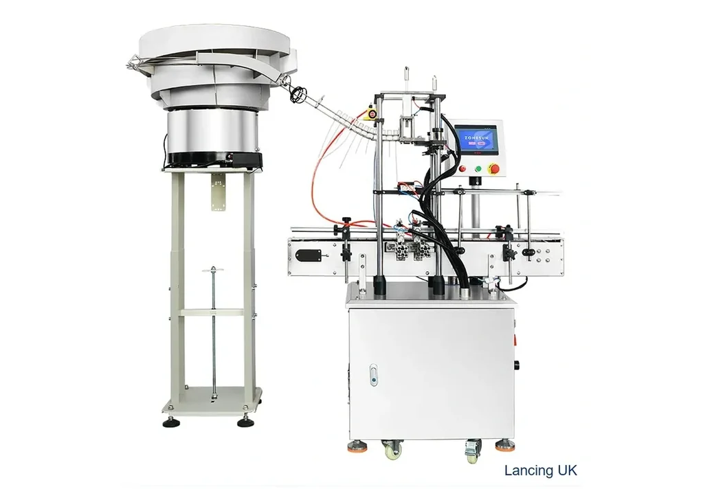
Automatic screw capper
Bowl-feed automatic screw capper
Automatic screw cap handling with bowl feeding for threaded closures where operator cap placement would limit line speed or consistency.
Ask about this machine →Cap bowl feeders, elevators and placement systems for screw caps, pumps, trigger closures and press caps.
The right capping system depends on closure geometry, bottle stability, torque or seating requirement, cap presentation and integration with your existing line.
Automatic screw cap handling with bowl feeding for threaded closures where operator cap placement would limit line speed or consistency.
Ask about this machine →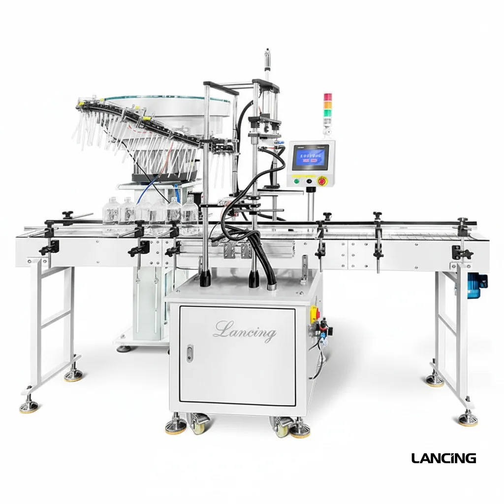
Specialist pump-cap feeding and placement support for difficult pump and dispenser closures that need correct orientation before closing.
Ask about this machine →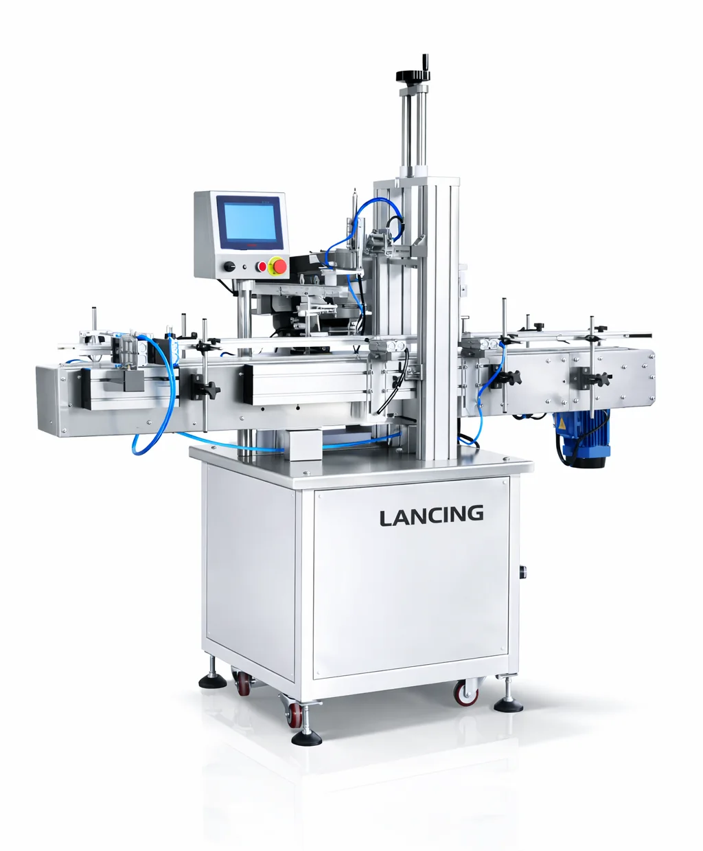
Press capping for push-on caps, lids and cover-style closures where vertical seating force and repeatable cap presentation are critical.
Ask about this machine →Cap feeding often decides whether a line can move from semi-automatic to automatic capping. The cap must arrive correctly oriented, at the right rate and without damaging liners, skirts or trigger heads.
Options include vibratory bowl feeders, centrifugal sorters, cap elevators, pump-cap handling and manual placement for low-volume or complex closures.
Cap diameter, height, weight, material, closure geometry, liner type and output target all affect feeder selection and changeover requirements.
Photos, dimensions and target output help shortlist the correct machine. Physical samples can then be checked before the final capping specification is confirmed.
Most fully automatic capping systems need some form of cap feeding or cap presentation. Low-volume systems may still use manual cap placement.
Sometimes, but the cap shape, size range and orientation method need to be checked carefully to avoid unreliable feeding.
Automatic capping projects often depend as much on cap feeding as on the tightening head. A cap may be easy to tighten once placed but difficult to orientate, separate, pick or transfer at the required pace.
| Feeding point | What to check | Why it affects the capping machine |
|---|---|---|
| Bulk cap behaviour | Caps nesting, tangling, static, deformation or inconsistent moulding. | Controls whether a bowl, elevator, pick-and-place or manual placement route is practical. |
| Orientation | Threaded side, nozzle direction, trigger head angle, dip tube and cap top geometry. | Incorrect orientation can stop automatic placement even when the capping head is suitable. |
| Transfer to bottle | Track exit, chute, pick head, cap starwheel or operator presentation. | Determines whether the cap meets the bottle squarely before torque or press force is applied. |
| Line control | Sensor positions, bottle spacing, cap present checks, missing cap handling and conveyor stops. | Prevents capper faults from affecting filling, labelling and accumulation. |
Cap feeding is often the limiting factor on an automatic capping line. The closure must be suitable for orientating, storing, transferring and presenting at the capping head without jamming, nesting or arriving in the wrong position.
| Cap-feeding check | Evidence to provide | Possible result |
|---|---|---|
| Bulk behaviour | A representative quantity of caps, including caps from the same supplier and finish as production. | Shows whether caps nest, bridge, mark, stick together or need a different feed route. |
| Orientation | Photos of the top, skirt, thread, liner, pump stem or trigger head, plus physical samples where possible. | Confirms whether bowl feeding, elevator feeding or controlled pick-and-place handling should be considered. |
| Transfer to bottle | Bottle dimensions, neck finish, cap height and the proposed conveyor route. | Helps determine whether guides, side belts, pick-up tooling or presentation hardware are required. |
| Operator access | Expected cap loading method, changeover frequency and cleaning or inspection access requirements. | Affects hopper position, guarding, reach-in access and daily setup checks. |
| Line control | Where the capper should stop, wait, reject or alarm if caps are missing or bottles back up. | Prevents downstream pressure and reduces the risk of uncapped or poorly capped bottles continuing through the line. |
Cap feeding should be proven as a material-handling process using production closures, realistic replenishment and the intended capper demand.
A closure is easier to feed automatically when it can be separated, oriented and transferred consistently without nesting, tangling, sticking, deforming or presenting several stable wrong-way positions. Size alone is not enough; geometry, centre of gravity, surface finish, liner, tamper band and attachments all influence the feed route.
Test production closures rather than ideal samples. Long dip tubes, soft skirts, hinged features and highly polished surfaces may require controlled handling beyond a standard bowl or elevator. The trial should show how misoriented or damaged caps leave the system and how the feeder recovers after replenishment.
Compare cap feeding methods →The feeder must provide caps at a stable rate above normal capper consumption while retaining enough buffer to absorb short interruptions. Capacity should be assessed with the real closure and transfer route, not from the feeder drive speed alone.
Consider the usable oriented-cap rate, chute capacity, sensor positions, capper acceleration, rejected caps and the operator replenishment cycle. Excess feeder speed can create pressure and scuffing, while insufficient capacity causes starvation. Controls should modulate feed rather than relying on constant maximum output.
A full chute should cause the feeder to pause or reduce output before caps are compressed, overlapped or damaged. The capper may continue drawing from the buffered chute, and the feeder should restart automatically when the level falls to the agreed point.
The sensor arrangement needs to distinguish a healthy full buffer from a jammed transfer. Test the high-level response, restart delay and repeated cycling with the real caps. A chute that remains under excessive pressure can change cap orientation and cosmetic condition before application.
Yes. Small changes in moulding, ovality, flash, static, coating, liner position or tamper-band condition can alter how caps separate and travel through a feeder. A feeder approved on one batch should therefore be assessed against the normal production variation expected from the closure supply chain.
Retain the identity of trial batches and record any sensitivity found. When a later batch causes jams, compare components before changing feeder settings. The most useful evidence includes good and problematic samples, photographs of the jam position and the operating conditions at the time.
Qualify packaging variation before production →Send representative closure batches, expected replenishment method, target capper demand and photographs of the proposed line area for a practical feeding review.
Request capping advice