
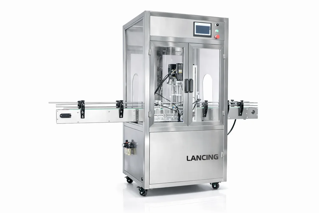
Automatic capping machines for bottle production lines
Move from manual cap placement to an automatic capping route designed around your closure, bottle stability, output target and downstream packaging line.
Ask about this application →Move from manual cap placement to an automatic capping route designed around your closure, bottle stability, output target and downstream packaging line.
Lancing can help shortlist practical capping machinery after reviewing cap type, neck finish, bottle stability, output target, torque requirement and the way caps are presented to the machine.

Move from manual cap placement to an automatic capping route designed around your closure, bottle stability, output target and downstream packaging line.
Ask about this application →Automatic capping is normally considered when operator placement is restricting output, when torque consistency needs tighter control or when cap feeding can remove a repetitive manual step. The correct machine depends on the closure family first, not just the required speed.
Automatic lines can be based around inline screw cappers, belt and spindle cappers, ROPP heads, pump cappers, trigger cappers, bowl feeders, cap elevators and guided conveyor systems. The cap presentation method should be specified with the machine.
Send bottle dimensions, cap diameter, cap height, cap material, target bottles per minute and details of your existing filler, labeller or conveyor. These points help decide whether the line needs starwheels, side belts, indexing or continuous motion handling.
Photos, dimensions and target output help identify the most likely capping route. Physical samples are normally the best way to confirm tooling, cap feeding and bottle support.
Not always. Some compact automatic machines can still use manual placement, but cap feeding is usually considered when production speed, labour use or consistency becomes the limiting factor.
Often yes, but bottle guides, grippers, belts, starwheels and capping heads may need adjustment or change parts for each bottle and closure format.
Output depends on cap style, bottle stability, feed route and line layout. Lancing can shortlist practical options once samples and target output are confirmed.
The visible machine examples on this page are a starting point. Final selection depends on samples and line information, especially where a cap looks simple but behaves differently under torque, pressure, feeding or conveyor handling.
Check cap diameter, cap height, liner, thread or seating method, bottle neck finish, bottle material and how firmly the container can be held while the closure is applied.
Confirm whether caps will be placed by hand, presented from a bowl, elevated from bulk storage or orientated by a custom track. Feeding can be the limiting factor on automatic systems.
Agree how a good cap will be checked: torque, tamper-band formation, seated height, leak risk, visual alignment, operator access and repeatability during changeover.
Compare this route with the parent closure technology guide, the capping route matrix, the torque and quality guide and the quote checklist. For deeper specialist information use the closure comparison where the closure type is already confirmed.
Send bottle and cap detailsAutomatic capping is most reliable when cap presentation, bottle control and line stop/start logic are designed together. The capper should not be treated as a separate island if the filler, conveyor, labeller or accumulation table controls the flow of bottles.
| Interface point | What to confirm | Why it matters |
|---|---|---|
| Filler discharge | Bottle spacing, product residue around the neck, container stability and whether bottles arrive continuously or in batches. | Inconsistent spacing or contamination around the finish can create capping variation. |
| Cap feeder | Cap geometry, orientation route, feed track stability, refill access and sensor position. | The capper can only run as consistently as the cap supply feeding it. |
| Bottle handling | Side belts, guides, starwheels, grippers or pucks depending on bottle shape and stiffness. | A moving or rotating bottle can create low torque, skewed caps or cross-threading. |
| Downstream equipment | Labeller infeed, coder position, checkweigher or accumulation after capping. | Downstream stops must not cause pressure or bottle damage around the capping area. |
| Quality checks | Torque method, cap-height check, visual inspection, tamper-band check or leak check depending on closure type. | Acceptance criteria should be agreed before the final machine route is confirmed. |
An automatic capping line is not complete when it can place and tighten a cap under ideal conditions. The scope should also define what the machine can detect, how it responds to a fault and how production restarts without releasing unchecked packs.
| Condition | Questions for the controls scope | Evidence needed at acceptance |
|---|---|---|
| No container at the capping position | Will the cap be withheld, recycled, rejected or allowed to fall, and how is the condition detected? | Repeated empty-position trials at the agreed operating pattern. |
| Container present but cap absent | Can the system detect the missing cap before or after the capping head, and is stop, alarm or rejection appropriate? | Known missing-cap samples passed through the agreed inspection point. |
| Poorly seated or tilted cap | Which defects are physically detectable and which require torque, vision or offline sampling? | Challenge samples representing the defects the system is expected to identify. |
| Downstream blockage | How much accumulation is available and how will the capper slow or stop without compressing unstable bottles? | Controlled stop-and-restart testing with the downstream machine unavailable. |
| Reject confirmation failure | Does the line stop when a commanded reject is not confirmed, and where are rejected packs collected? | A reject challenge that confirms detection, removal and bin/route control. |
Not every fault can be detected by a simple sensor, and inspection technology should not be described as proof of closure integrity unless the method has been validated for the real pack. Define the required risk control, test it with representative good and defective samples, and record any faults that remain dependent on offline checks.
Automatic capping performance depends on fault response, cap supply, recovery and the wider line as well as the tightening mechanism itself.
The line should detect low cap availability early enough to avoid sending uncapped containers through the tightening station. The preferred response depends on the line design: it may warn the operator, pause container release, stop the capper in a controlled state or coordinate a stop with the filler and downstream equipment.
Define the low-level sensor, chute-full condition, time available for replenishment and restart sequence before controls are finalised. A feeder that simply runs until empty can create mixed good and uncapped product, unnecessary rejects and difficult recovery. The correct logic should be demonstrated with real caps during acceptance testing.
Plan capping line controls →Rated speed describes a machine capability under stated conditions; sustained line output is the good product actually produced over an agreed period with normal feeding, stops, checks and operator tasks. The two figures differ when cap replenishment, bottle accumulation, rejects, changeovers or surrounding machinery constrain the capping stage.
Specify both the target rate and the conditions used to prove it. Record pack format, cap feed method, upstream supply, downstream availability, inspection frequency and permitted interventions. This makes quotations and factory acceptance discussions more comparable.
Define realistic capping output →Faults that can create unsafe operation, uncontrolled damage, repeated missing caps or loss of the agreed quality method normally need a defined stop or reject response. The exact list must be risk assessed for the application and linked to sensors that can detect the condition reliably.
Typical control discussions include guard opening, overload, bottle jam, no-cap condition, feeder fault, outfeed blockage and reject-system failure. Not every quality defect can be detected automatically, so the project should separate machine-protection logic, pack-inspection logic and scheduled manual quality checks.
Define inspection and reject responses →Operators should usually be able to clear routine cap or bottle interruptions, replenish caps, remove identified rejects and restart the approved format without altering protected torque, tooling or safety parameters. The permitted actions should be defined in the operating procedure and supported by clear controls and access.
Recovery that requires trial-and-error adjustment creates variation between shifts. Separate normal operator actions from supervisor setup and engineering maintenance. After a significant jam or intervention, require the same first-off checks used at start-up before unrestricted production resumes.
Share the cap feed route, line interfaces, fault philosophy and target sustained output so the capping proposal can include practical controls and recovery.
Request capping adviceThe published configuration uses side-belt control, PLC/touchscreen operation and optional elevator or vibratory-bowl cap feeding for compatible screw closures.
Review the LU-XG440B-class specification →The published capacity is a screening range. A sustained result depends on cap supply, bottle stability, product condition, changeovers and the agreed inspection method.
Define a meaningful output test →Confirm conveyor heights, accumulation, upstream filler behaviour, downstream inspection and the control response to cap starvation or blocked outfeed.
Plan line controls and integration →